Nat
Содержание:
Ближнее Прохождение NAT
Модули SIP и XIMSS CommuniGate Pro определяют запросы на установление сессии, отправленные от одной стороны через NAT другой стороне (запрос от клиента в локальной сети, направляемый участнику в Интернет/WAN и наоборот). В этом случае сервер использует специальный локальный порт сервера (или набор таких портов, в зависимости от используемого медиа протокола) и осуществляет проксирование медиа данных. Сервер изменяет запросы на установление сессии и направляет трафик обеих сторон через такой прокси.
Медиа Прокси ретранслирует медиа данные между «плечом LAN» и «плечом WAN» медиа соединения:
Модули SIP и XIMSS CommuniGate Pro определяют запросы на изменения сессии (команду re-INVITE протокола SIP) и запросы на закрытие сессии (команду BYE протокола SIP) и, соответственно, изменяют или удаляют Медиа Прокси. Для удаления «заброшенных» Медиа Прокси используется механизм тайм-аутов.
CommuniGate Pro обеспечивает услуги проксирования NAT для:
- UDP медиа протоколов
- RTP медиа протоколов, основывающихся на UDP
- TCP медиа протоколов
- T.120 медиа протоколов, основывающихся на TCP
Обратите внимание: Если вам необходимо использовать функции Проксирования Медиа, убедитесь, что данные о конфигурации LAN и NAT на странице с настройками Адреса LAN и заданы корректно. Обратите внимание: Сервер автоматически выполняет Медиа Проксирование при ретрансляции запросов, приходящих с IPv4 адресов на IPv6 адреса и наоборот
Обратите внимание: Сервер автоматически выполняет Медиа Проксирование при ретрансляции запросов, приходящих с IPv4 адресов на IPv6 адреса и наоборот
References
Overview:
- http://www.cisco.com/en/US/partner/technologies/tk648/tk361/tk438/technologies_white_paper09186a0080091cb9.html
- Anatomy: http://www.cisco.com/web/about/ac123/ac147/archived_issues/ipj_7-3/anatomy.html
- http://www.cisco.com/en/US/tech/tk648/tk361/technologies_tech_note09186a0080094831.shtml
VoiP and NAT
- https://supportforums.cisco.com/docs/DOC-5406
- http://www.juniper.net/techpubs/software/junos-security/junos-security95/junos-security-swconfig-security/id-60290.html
NAT Feature Matrix
- http://www.cisco.com/en/US/tech/tk648/tk361/technologies_tech_note09186a0080b17919.shtml
- http://www.cisco.com/en/US/technologies/tk648/tk361/tk438/technologies_white_paper09186a00801af2b9.html
- http://www.cisco.com/en/US/tech/tk648/tk361/technologies_tech_note09186a0080b17919.shtml
Hosted NAT traversal:
www.tmcnet.com/it/0804/FKagoor.htm
NAT SBC
- EDCS-611622
- EDCS-526070
ALG:
- http://www.cisco.com/en/US/docs/ios-xml/ios/ipaddr_nat/configuration/15-0s/iadnat-applvlgw.html
- http://www.voip-info.org/wiki/view/Routers+SIP+ALG
- http://www.commpartners.us/knowledge/attachments/voip-nat.pdf
- http://www.cisco.com/en/US/partner/docs/ios-xml/ios/ipaddr_nat/configuration/15-mt/nat-tcp-sip-alg.html
CME
- http://www.cisco.com/en/US/docs/routers/asr1000/configuration/guide/sbcu/sbc_cucm.html
Case 2
In this scenario, we see that if fragments other than the first fragment (fragment 0) arrive first, NAT creates a simple translation as long as there is an address in the NAT pool that has not already been used in a fully extended translation.
As we start, there is only one address in the NAT pool, the NAT translation table is empty, and the configuration appears as:
-
Packet 1 fragment 1 arrives. NAT can’t create a fully extended translation in the translation table since it doesn’t have the ICMP ident information in this fragment. However, since there aren’t any fully extended translations in place, NAT enters a simple translation. NAT then translates and forwards packet 1 fragment 1. The translation entry appears as:
-
Packet 1 fragment 0 arrives. Since the ICMP ident information is included in this fragment, NAT enters a fully extended translation entry:
NAT then records the IP ident information, and translates and forwards packet 1 fragment 0.
-
Packet 1 fragment 2 arrives. Because this fragment has the same IP ident information that NAT recorded in step 2, NAT uses the fully extended translation to translate and forward packet 1 fragment 2.
The destination device receives all fragments and replies. At this point, all pings succeed until the NAT translation table is cleared or times out.
Troubleshoot
This section provides information you can use to troubleshoot your configuration.
Troubleshooting Commands
The Output Interpreter Tool (registered customers only) (OIT) supports certain show commands. Use the OIT to view an analysis of show command output.
Note: Refer to Important Information on Debug Commands before you use debug commands.
-
debug ip nat—Displays information about IP packets translated by the IP NAT feature.
-
clear ip nat translation *—Clears dynamic Network Address Translation (NAT) translations from the translation table.
Related Commands
-
ip nat—Designates that traffic which originates from or destined for the interface is subject to NAT.
-
ip nat inside destination—Enables NAT of the inside destination address.
-
ip nat inside source—Enables NAT of the inside source address.
-
ip nat outside source—Enables NAT of the outside source address.
Configure
In this section, you are presented with the information to configure the features described in this document.
Note: To find additional information on the commands used in this document, use the Command Lookup Tool (registered customers only) .
Network Diagram
This document uses this network setup:
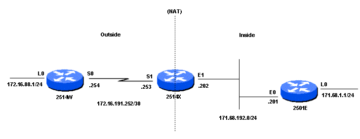
When ping is sourced from the Router 2514W Loopback0 interface (172.16.88.1) to the Router 2501E Loopback0 interface (171.68.1.1), this occurs:
The Router 2514W forwards the packets to Router 2514X because it is configured with a default route. On the outside interface of Router 2514X, the packet has a source address (SA) of 172.16.88.1 and a Destination Address (DA) of 171.68.1.1. Because the SA is permitted in access-list 1, which is used by the ip nat outside source list command, it is translated to an address from the NAT pool Net171. Notice that the ip nat outside source list command references the . In this case, the address is translated to 171.68.16.10 which is the first available address in the NAT pool. After translation, Router 2514X looks for the destination in the routing table, and routes the packet. Router 2501E sees the packet on its incoming interface with a SA of 171.68.16.10 and a DA of 171.68.1.1. It responds by sending an Internet Control Message Protocol (ICMP) echo reply to 171.68.16.10. If it doesn’t have a route, it drops the packet. In this case, it has a (default) route, so it sends a packet to Router 2514X, using an SA of 171.68.1.1 and a DA of 171.68.16.10. Router 2514X sees the packet on its inside interface and checks for a route to the 171.68.16.10 address. If it does not have one, it responds with an ICMP unreachable reply. In this case, it has a route to , due to the add-route option of the ip nat outside source command which adds a host route based on the translation between the outside global and outside local address, so it translates the packet back to the 172.16.88.1 address, and routes the packet out its outside interface.
Configurations
| Router 2514W |
|---|
hostname 2514W ! interface Loopback0 ip address 172.16.88.1 255.255.255.0 ! interface Serial0 ip address 172.16.191.254 255.255.255.252 no ip mroute-cache ! ip classless ip route 0.0.0.0 0.0.0.0 172.16.191.253 ! |
| Router 2514X |
|---|
hostname 2514X ! ! interface Ethernet1 ip address 171.68.192.202 255.255.255.0 ip nat inside no ip mroute-cache no ip route-cache ! interface Serial1 ip address 172.16.191.253 255.255.255.252 ip nat outside no ip mroute-cache no ip route-cache clockrate 2000000 ! ip nat pool Net171 171.68.16.10 171.68.16.254 netmask 255.255.255.0 ! ip nat outside source list 1 pool Net171 add-route ip classless ip route 172.16.88.0 255.255.255.0 172.16.191.254 ip route 171.68.1.0 255.255.255.0 171.68.192.201 access-list 1 permit 172.16.88.0 0.0.0.255 ! ! |
| Router 2501E |
|---|
hostname 2501E ! interface Loopback0 ip address 171.68.1.1 255.255.255.0 ! interface Ethernet0 ip address 171.68.192.201 255.255.255.0 ! ip classless ip route 0.0.0.0 0.0.0.0 171.68.192.202 ! |
Term Definitions
Cisco defines these terms as:
-
Inside local address—The IP address assigned to a host on the inside network. This is the address configured as a parameter of the computer OS or received via dynamic address allocation protocols such as DHCP. The address is likely not a legitimate IP address assigned by the Network Information Center (NIC) or service provider.
-
Inside global address—A legitimate IP address assigned by the NIC or service provider that represents one or more inside local IP addresses to the outside world.
-
Outside local address—The IP address of an outside host as it appears to the inside network. Not necessarily a legitimate address, it is allocated from an address space routable on the inside.
-
Outside global address—The IP address assigned to a host on the outside network by the host owner. The address is allocated from a globally routable address or network space.
These definitions still leave a lot to be interpreted. For this example, this document redefines these terms by first defining local address and global address. Keep in mind that the terms inside and outside are NAT definitions. Interfaces on a NAT router are defined as inside or outside with the NAT configuration commands, and . Networks to which these interfaces connect can then be thought of as inside networks or outside networks, respectively.
-
Local address—A local address is any address that appears on the inside portion of the network.
-
Global address—A global address is any address that appears on the outside portion of the network.
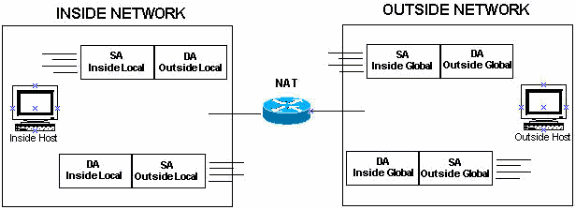
Packets sourced on the inside portion of the network have an inside local address as the source address and an outside local address as the destination address of the packet, while the packet resides on the inside portion of the network. When that same packet gets switched to the outside network, the source of the packet is now known as the inside global address and the destination of the packet is known as the outside global address.
Conversely, when a packet is sourced on the outside portion of the network, while it is on the outside network, its source address is known as the outside global address. The destination of the packet is known as the inside global address. When the same packet gets switched to the inside network, the source address is known as the outside local address and the destination of the packet is known as the inside local address.
This image provides an example.
NAT: общие определения
NAT (network address translation) или трансляция сетевых адресов — это процесс перевода внутренних или локальных адресов во внешние. NAT используется абсолютно всеми маршрутизаторами независимо от их конфигурации, назначения и стоимости. По умолчанию роутер запрещает напрямую обращаться к любому устройству, находящимися внутри сети. Он блокирует доступ на любые порты для входящих соединений поступающие из интернета.
Но NAT и Firewall это суть разные понятия. Firewall просто запрещает доступ к ресурсу по определенному TCP или UDP порту, может устанавливаться на локальной машине для ограничения доступа только к ней или же на сервере для фильтрации трафика по всей локальной сети. Перед NAT задача стоит более развернуто. Сервис запрещает или разрешает доступ внутри сети по конкретному IP адресу или диапазону адресов. Таким образом клиент, который обращается к ресурсу не видит действительного IP адреса ресурса. NAT переводит внутренний IP в адрес, который будет виден из интернета.
Чтобы проверить находится ли компьютер за NAT или транслирует в интернет реальный адрес можно следующим образом:
- в Windows нужно нажать «Пуск — Выполнить — cmd» и прописать ipconfig и нажать «Ввод»;
- в Linux и MacOS в терминале выполняется ifconfig.
Вывод команды показывает следующие данные:
- IP — реальный, действительный адрес компьютера;
- Subnet mask — маска подсети;
- Gateway — адрес шлюза маршрутизатора.
Как теперь разобрать является ли адрес локальным или же напрямую «смотрит» в интернет. Согласно спецификации, существует четыре диапазона адресов, которые ни при каких обстоятельствах не используются в интернете, а являются исключительно локальными:
- 0.0.0 — 10.255.255.255
- Х.0.0 — 172.Х.255.255, где Х в диапазоне от 16 до 31.
- 168.0.0 — 192.168.255.255
- 254.0.0 — 169.254.255.255
В том случае, когда адрес машины попадает в один из этих диапазонов, следует считать, что компьютер находится в локальной сети или «за» NAT. Можно также дополнительно использовать специальные службы, которых есть множество в интернете для определения реального IP адреса. Теперь стало понятнее находится ли компьютер за NAT в роутере что это за сервис, и за то он отвечает.
Пример: Разрешение доступа в Интернет внутренним пользователям
Возможно, вы хотите предоставить доступ в Интернет внутренним пользователям, но у вас нет достаточного количества допустимых адресов. Если все взаимодействия с Интернет-устройствами возникают из внутренних устройств, то нужен один допустимый адрес или пул допустимых адресов.
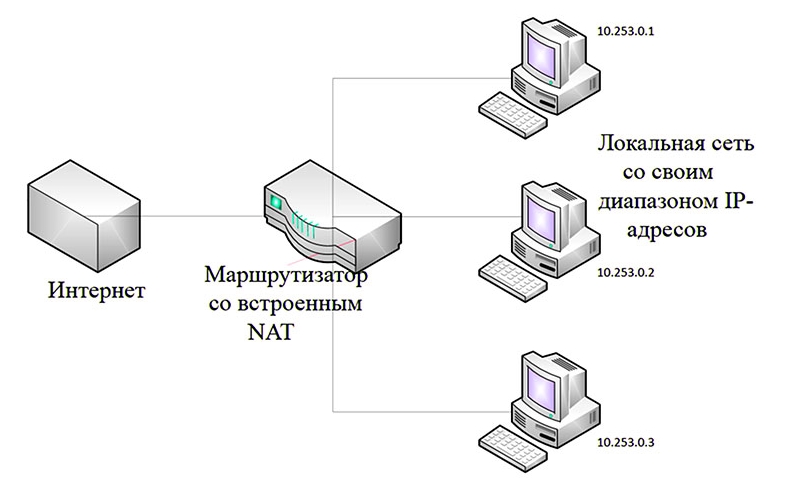
На следующем рисунке показана схема простой сети с внутренним и внешним интерфейсами маршрутизатора:
В этом примере NAT нужен затем, чтобы разрешить определенным внутренним устройствам (первым 31 из каждой подсети) создать связь с устройствами снаружи, преобразуя их недопустимый адрес в допустимый адрес или пул адресов. Пул задан как диапазон адресов от 172.16.10.1 до 172.16.10.63.
Теперь можно приступить к настройке NAT. Для выполнение описанных выше действий используйте функцию динамического NAT. При динамической трансляции сетевых адресов таблица трансляции в маршрутизаторе исходно является пустой и начинает заполняться после того, как трафик для трансляции проходит через маршрутизатор. (В отличие от функции статического NAT, где трансляция настраивается статически и помещается в таблицу трансляции без присутствия трафика).
В этом примере можно настроить NAT для трансляции каждого внутреннего устройства на уникальный допустимый адрес или для трансляции всех внутренних устройств на один допустимый адрес. Второй метод известен как перегрузка. Пример настройки каждого метода приведен ниже.
Настройка NAT для разрешения доступа в Интернет внутренним пользователям
|
Маршрутизатор NAT |
|---|
interface ethernet 0 ip address 10.10.10.1 255.255.255.0 ip nat inside interface ethernet 1 ip address 10.10.20.1 255.255.255.0 ip nat inside interface serial 0 ip address 172.16.10.64 255.255.255.0 ip nat outside ip nat pool no-overload 172.16.10.1 172.16.10.63 prefix 24 ! ip nat inside source list 7 pool no-overload ! ! access-list 7 permit 10.10.10.0 0.0.0.31 access-list 7 permit 10.10.20.0 0.0.0.31 |
Примечание. Cisco настоятельно рекомендует не настраивать списки доступа, упоминаемые в командах NAT, с помощью команды permit any. Использование команды permit any может привести к тому, что NAT будет потреблять слишком большое количество ресурсов маршрутизатора, что вызовет проблемы с сетью.
В приведенной выше конфигурации следует отметить, что только первые 32 адреса из подсети 10.10.10.0 и первые 32 адреса из подсети 10.10.20.0 разрешены списком доступа 7 Таким образом, выполняется преобразование только этих исходных адресов. Внутренняя сеть может содержать другие устройства с другими адресами, которые не транслируются.
Последнее, что нужно сделать — это .
Additional References
The following sections provide references related to using application level gateways with NAT.
Related Documents
|
Related Topic |
Document Title |
|---|---|
|
NAT commands: complete command syntax, command mode, defaults, usage guidelines, and examples |
«IP Addressing Commands» chapter in the Cisco IOS IP Command Reference, Volume 1 of 3: Addressing and Services, Release 12.4T |
MIBs
|
MIBs |
MIBs Link |
|---|---|
|
None |
To locate and download MIBs for selected platforms, Cisco IOS releases, and feature sets, use Cisco MIB Locator found at the following URL: |
Technical Assistance
|
Description |
Link |
|---|---|
|
The Cisco Technical Support website contains thousands of pages of searchable technical content, including links to products, technologies, solutions, technical tips, and tools. Registered Cisco.com users can log in from this page to access even more content. |
Prerequisites
Requirements
Ensure that you meet these requirements before you attempt this configuration:
-
Familiarity with how NAT works.
Refer to How NAT Works for more information.
-
Familiarity with the commands to use in order to configure NAT on a router.
For more information on the commands, refer to Configuring Network Address Translation: Getting Started.
Components Used
The information in this document is based on the Cisco Catalyst 6500 Series Switch with Supervisor Engine 720 that runs Cisco IOS Software Release 12.2(18)SXD6 and the Cisco Catalyst 6500 Series Switch with Supervisor Engine II that runs CatOS Software Release 8.4(4).
The information in this document was created from the devices in a specific lab environment. All of the devices used in this document started with a cleared (default) configuration. If your network is live, make sure that you understand the potential impact of any command.
Case 3
In this scenario, we see that if fragments other than the first fragment (fragment 0) arrive first, NAT creates a simple translation as long as there is an address in the NAT pool that has not already been used in a fully extended translation. If an extended translation in the NAT table already uses the address, you run the risk of NAT translating each of the fragment source addresses to a different address.
As we start, more than one address in the NAT pool performs overload, the translation table already has an extended translation in place, and the configuration is:
The translation table appears as:
-
Packet 1 fragment 1 arrives. NAT can not create a fully extended translation table entry since it doesn’t have the ICMP ident information in this fragment, and it can’t create a simple translation entry for address 10.10.10.3, since there’s an existing extended entry for this IP address. NAT picks the next free IP address (10.10.10.4) and creates a simple translation. NAT then translates and forwards packet 1 fragment 1. The translation table now appears as:
-
Packet 1 fragment 0 arrives. Since the ICMP ident information is included in this fragment, NAT enters a fully extended translation entry for address 10.10.10.3, and records the IP ident information for this packet. NAT then translates and forwards packet 1 fragment 0. The translation table now appears as:
-
Packet 1 fragment 2 arrives. Since its IP ident information matches the one NAT recorded in step 2, NAT uses the fully extended translation created in step 2 to translate and forward packet 1 fragment 2.
At this point, the destination device receives all fragments of packet 1, but fragment 0 and 2 have had their source address translated to 10.10.10.3 and fragment 1 has been translated to 10.10.10.4. Therefore, the destination device can not reassemble the packet and sends no reply.
-
Packet 2 fragment 0 arrives. NAT either uses the above fully extended translation or creates a new fully extended translation depending on the value of the fragment ICMP ident field. In either case, NAT records the IP ident information. NAT then translates and forwards packet 2 fragment 0.
-
Packet 2 fragment 2 arrives. Its IP ident information matches what NAT recorded in step 4, so NAT uses the second fully extended translation created in step 4. NAT translates and forwards packet 2 fragment 2.
-
Packet 2 fragment 1 arrives. Its IP ident information matches what NAT recorded in step 4, so NAT uses the second fully extended translation created in step 4. NAT translates and forwards packet 2 fragment 1.
The destination device receives all three fragments of packet 2 from the same source (10.10.10.3), so it reassembles the packet and replies.
SNAT
Значение термина SNAT зависит от поставщика. Многие поставщики имеют собственные определения для SNAT :
- исходный NAT является обычным расширением, как аналог NAT назначения ( DNAT )
- NAT с отслеживанием состояния используется Cisco Systems
- статический NAT используется WatchGuard
- безопасный NAT используется F5 Networks и Microsoft (в отношении ISA Server )
Трансляция защищенных сетевых адресов (SNAT) от Microsoft является частью Microsoft Internet Security and Acceleration Server и является расширением драйвера NAT, встроенного в Microsoft Windows Server . Он обеспечивает отслеживание и фильтрацию подключений для дополнительных сетевых подключений, необходимых для протоколов FTP , ICMP , H.323 и PPTP , а также возможность настройки прозрачного прокси-сервера HTTP .
NAT in VoIP
So, what are the issues and concerns with NAT in VoIP networks? Well, recall that NAT that we have discussed so far (losely referredto as basic NAT) only translates the IP address in the IP packet header and re-calculates the checksum, of course, but VoIP signaling carry addresses embedded in the body of the signaling messages. In other words, at Layer 5
Figure 5 illustrates the effect of leaving the embedded IP addresses un-translated. The call signaling completes successful, but the SIP proxy at the service provider fails trying to route media (RTP) packets to media address sent by the call agent!

Figure 5
Another example would be SIP endpoint’s use of Contact: field in SDP to communicate the address at which the endpoint would like to receive signaling messages for new requests.
These issues are addressed by a feature called Application Layer Gateway (ALG).
Troubleshoot
Error Message Received When Adding a Static PAT for Port 443
Problem
You receive this error message when you add a static PAT for port 443:
static (INSIDE,OUTSIDE) tcp interface 443 192.168.1.87 443 netmask 255.255.255.255 tcp 0 0 udp 0
unable to reserve port 443 for static PAT
ERROR: unable to download policy
Solution
This error message occurs when either ASDM or WEBVPN is running on the 443 port. In order to resolve this issue, log in to the firewall, and complete one of these steps:
-
In order to change the ASDM port to anything other than 443, run these commands:
-
In order to change the WEBVPN port to anything other than 443, run these commands:
After you run these commands, you should be able to add a NAT/PAT on port 443 to another server. When you attempt to use ASDM to manage the ASA in the future, specify the new port as 8080.
ERROR: mapped-address conflict with existing static
Problem
You receive this error when you add a static statement on the ASA:
ERROR: mapped-address conflict with existing static
Solution
Verify that an entry does not already exist for the static source you want to add.
Типы NAT
Есть достаточно много разных вариантов технологии NAT. Мы рассмотрим 3 типа, которые используются чаще всего. Однако, кроме них есть и другие возможные варианты.
Статический NAT
Первый тип это статическое отображение ip адресов один к одному. В этом случае, нам нужно иметь столько же внешних адресов, сколько и компьютеров во внутренней сети. т.е. 4 компьютера и 4 ip адреса в нашем случае. И у нас фиксированное отображение внутренних адресов во внешние ip адреса.

Такая схеме используетя редко и она возможна, когда Вы подключаете сеть организации не к интернет, а к какой-то другой организации, где тоже используются внутренние ip адреса и возможен конфликт ip адресов.
Динамический NAT
Второй вариант это динамическое преобразование, когда набор внутренних ip адресов отображается на группу внешних ip адресов. В случае динамического NAT у нас есть несколько внешних ip адресов, которые поочередно используются разными компьютерами из внутренней сети. Например сначала компьютер 1 использует первый адрес, а компьютер 3 второй адрес.

Через некоторое время, второй компьютер может использовать второй адрес, а третий компьютер первый адрес. Таким образом, преобразование выполняется динамически.
Один ко многим (masquerading)
Третий вариант, который используется чаще всего это, когда все адреса из внутренней сети, отображаются на один внешний ip адрес.
Рассмотрим, как работает вариант NAT one-to-many, потому что с его помощью, можно подключать к интернет большие сети организаций, используя один внешний ip адрес (184.86.48.128). Именно это позволяет частично смягчить проблему нехватки адресов ipv4.

Преобразование или трансляция сетевых адресов, реализуется с помощью таблицы NAT, которая находится внутри устройства NAT.

Заключение
Настройка ASA для выполнения базовой NAT — не такая сложная задача. Приведенный в этом документе пример можно адаптировать к конкретному сценарию, если изменить IP-адреса и порты, используемые в примерах конфигурации. Окончательная конфигурация ASA при сочетании всего этого выглядит примерно так для ASA 5510:
ASA Version 9.1(1)!interface Ethernet0/0 nameif outside security-level 0 ip address 198.51.100.100 255.255.255.0!interface Ethernet0/1 nameif inside security-level 100 ip address 192.168.0.1 255.255.255.0!interface Ethernet0/2 nameif dmz security-level 50 ip address 192.168.1.1 255.255.255.0!object network inside-subnet subnet 192.168.0.0 255.255.255.0object network dmz-subnet subnet 192.168.1.0 255.255.255.0object network webserver host 192.168.1.100object network webserver-external-ip host 198.51.100.101object network dns-server host 192.168.0.53!access-list outside_acl extended permit tcp any object webserver eq wwwaccess-list dmz_acl extended permit udp any object dns-server eq domainaccess-list dmz_acl extended deny ip any object inside-subnetaccess-list dmz_acl extended permit ip any any!object network inside-subnet nat (inside,outside) dynamic interfaceobject network dmz-subnet nat (dmz,outside) dynamic interfaceobject network webserver nat (dmz,outside) static webserver-external-ip service tcp www wwwaccess-group outside_acl in interface outsideaccess-group dmz_acl in interface dmz!route outside 0.0.0.0 0.0.0.0 198.51.100.1 1
На ASA 5505, например, с интерфейсами, подключенными, как показано ранее (outside подключен к Ethernet0/0, inside к Ethernet0/1, а DMZ к Ethernet0/2):
ASA Version 9.1(1)!interface Ethernet0/0 description Connected to Outside Segment switchport access vlan 2!interface Ethernet0/1 description Connected to Inside Segment switchport access vlan 1!interface Ethernet0/2 description Connected to DMZ Segment switchport access vlan 3!interface Vlan2 nameif outside security-level 0 ip address 198.51.100.100 255.255.255.0!interface Vlan1 nameif inside security-level 100 ip address 192.168.0.1 255.255.255.0!interface Vlan3 nameif dmz security-level 50 ip address 192.168.1.1 255.255.255.0!object network inside-subnet subnet 192.168.0.0 255.255.255.0object network dmz-subnet subnet 192.168.1.0 255.255.255.0object network webserver host 192.168.1.100object network webserver-external-ip host 198.51.100.101object network dns-server host 192.168.0.53!access-list outside_acl extended permit tcp any object webserver eq wwwaccess-list dmz_acl extended permit udp any object dns-server eq domainaccess-list dmz_acl extended deny ip any object inside-subnetaccess-list dmz_acl extended permit ip any any!object network inside-subnet nat (inside,outside) dynamic interfaceobject network dmz-subnet nat (dmz,outside) dynamic interfaceobject network webserver nat (dmz,outside) static webserver-external-ip service tcp www wwwaccess-group outside_acl in interface outsideaccess-group dmz_acl in interface dmz!route outside 0.0.0.0 0.0.0.0 198.51.100.1 1